Build Your Own Torque Meter

Building your own torque meter is much, much easier than building your last model. It does have a bit of mystique though. I will describe it without any confusing discussion of formulae, torsional modulus, or other intimidating engineering phrases. If you need all the science, I have some technical stuff I saved for just such an occasion. I have never read it though, so be careful if you choose to. For starters let's just do it the old fashion way, by cutting, filing, and soldering, or even glueing if you don't have a soldering iron. I won't bother with accurate dimensioning so as to remind you constantly that this is not rocket science. We are just playing with gummy band model planes, not going to Mars. First off, torque is the measure of twisting energy. As rubber flyers, we care about it because it gives us an idea of how much energy is wound into a rubber motor. By keeping a few notes, we can optimise our motors for a given ceiling height, or wind them to within an inch (or ounce/inch) of their life, and not destroy a model in the process. You know what I mean, you feel the motor getting tight, and the old 5 fingered biotorquemeter hasn't been calibrated lately. Suddenly the winder handle gets all too limp in your hand. About that same time, you hear a sickening scrunch as the uprights and cross pieces of your fuselage are "adjusted". On a great day the fragments of rubber do their best to make confettii of your latest wrinkle free finish. Try a torque meter. Your buddies will have much less opportunity to yell out, "Hey stupid, back off a turn or two." Now that you know you need one, let's get started. |
|
|
|---|
|
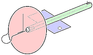
Design: The heart of a torque meter is nothing more than a bent piece of music wire as shown above. Typically these are around 6" long for stationary meters. The diameter of the wire depends on what kind of models you are flying. Something skinny like 0.015 might be good for light indoor models, or .020 - 0.025 for medium sized sport models and perhaps 0.032 for large outdoor models. Basically you don't want to twist the wire more than about 300-360 degrees in use. Remember that length will affect the neede wire size as well. A quick test with a motor and a winder will tell you if you have the right size wire.
You can bend the right hook for the rubber now, but hold off until assembly to bend the straight leg that anchors it in the tube. We still need a couple other components. A convenient holder, a pointer and some sort of scale will complete our meter. Let's use a bit of notched brass tubing to hold the wire. Solder a piece of sheet to the tube near one end, so that the finished meter can be screwed or clamped to a table or model box. The tube should be an inch or so shorter than the wire. Next, a pointer needs to be attached to the front of the wire as a pointer. This can be soldered or glued, just make sure it is firmly fixed. Finally we need a scale. This can be as simple as a scrap of cardboard with a few pencil marks on it. I think all your hard work will be more appreciated though, if you use something a bit more durable. A piece of brass sheet works well, as we are already in metal mode. If you like, substitue a nice piece of varnished wood. The scale can be permanently fixed to the tube, but that makes periodic maintenance tough. Try devising a nice friction fit on the tube. Perhaps a piece of the next larger telescoping brass tubing, ever so slightly squashed so that it holds the main tube firmly. The hole in the scale should be large enough to accomodate a nylon prop bearing, easily aquired from Peck Polymers or made at home. This is because you want zero friction for the wire. Assembly: Slide the scale and the bearing onto the main tube. Now slide the wire and pointer into the bearing. Finally bend up the rear leg of the wire to engage the slot in the tube. This can be soldered in place, or held with a drop or two of some glue you can soften in the future like Ambroid. Do your soldering or gluing with the tube held vertically so that it doesn't gum up the works inside the tube. Calibration: Remember you don't need to know exactly how many angstrom/tons of torque you are developing. You just need some marks so you can reference a given torque in the future. First, make a mark where the needle is with the meter at rest. Now, make an evenly spaced series of marks around the perimeter of the dial. Number them if you feel like it. Yup, that's it, you're done. Stand back and admire your work, and be proud. Wind a motor or two and watch the needle move. Wind a motor until it breaks, and notice how the needle really moves quickly right before the motor breaks. "Hey wait a minute!? What happens if my motor goes inside the model?" I see you figured it out too. The meter described above is best used for things like stick models where you can easily load the motor after winding. With one simple change, it can work great for models with a 3-D fuselage as well. If the main wire is double ended, as shown below, you can hook one end to the motor, and the other to the winder.
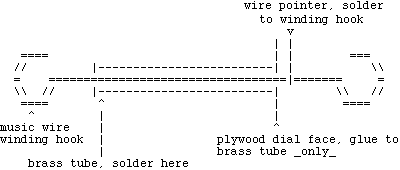
Instead of using a drop of glue at the back to hold the bent leg in a notch, you probably are best off soldering the wire to the main tube. But hey, you don't need to make or solder the hold down strap. This type of meter offers even more protection for your models. If you make the meter longer than the longest nose to motor peg distance of your models, you can use a blast tube inside the model while winding. A blast tube is nothing more than piece of the largest diameter tubing that will fit down the throat of your model. You slide it over the rubber motor while winding, and then just before hooking up your prop, you slide the tube out of the model and onto the back of the torque meter. The length of the meter needs to be longer than this tube, so you can unhook the meter and hook up the prop. It is a lot easier to do than to describe. To prove it is simple, I am going to add a super hightech ASCII text illustration from Dennis Weatherly to illustrate the modification. It is a side view cross section and easier to make than what I described. He even recommends gluing the dial to the tube.
 postscript - My personal meter has a swiveling pedestal mount that I thought was a good idea at the time. It sure seemed sexy as I was building it. More often than not, it complicates the operation of the meter. When I make another meter, it will not have that extra complexity. The Jim Jones meter doesn't have any fancy swivels. Simple is often the best. Can't get enough? You can now proceed with caution to the technical stuff. Actually, there is a lot that isn't technical also. I recommend it. |
Copyright 1999-2016, Thayer Syme.
All rights reserved